

[ Selected work ]
We don't publish client names, locations, or identifying details — every project we take on is covered by confidentiality, and yours would be too. What we can describe is the technical problem, what we did about it, and the outcome.
01
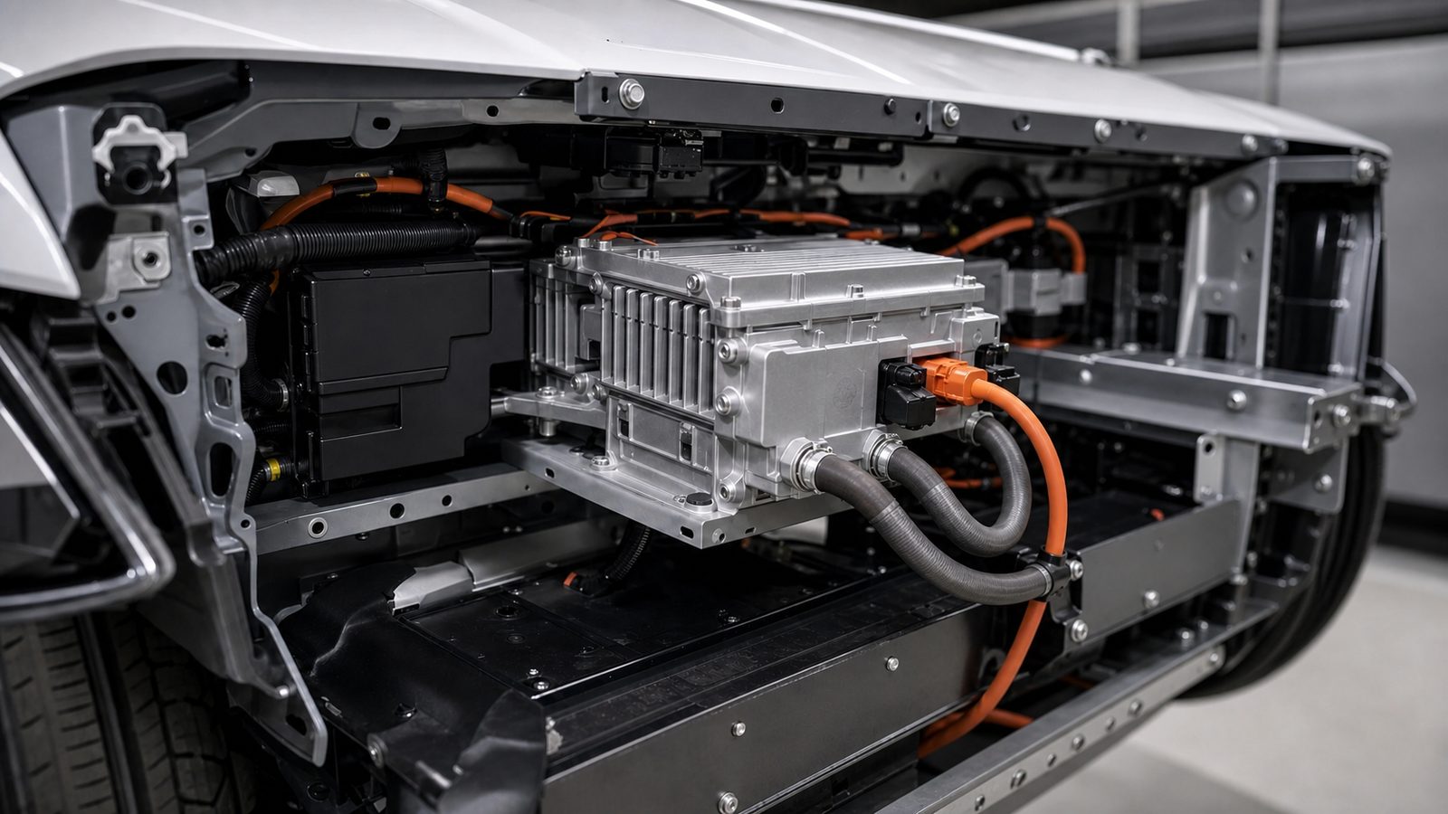
Package space in a vehicle is decided early and it does not grow. Our client, a Tier 1 supplier, had an 11 kW onboard charger for an 800 V architecture that met its electrical specification but not the volume and mass budget the program had allocated. Every fix that preserved the existing architecture gave up something the OEM would not: efficiency, thermal margin, or a qualification cycle already paid for.
Two requirements pushed the wrong way. An 800 V bus raises creepage and clearance, widens isolation barriers, and lifts device voltage ratings. Designing the power stage to run in reverse, so the platform can support V2H and V2G later, adds active devices, gate drive, and sensing where a one-directional design leaves the converter passive. The target was a much smaller board while the requirements argued for a bigger one.
Most of the volume in an onboard charger sits in the magnetics, the filtering, and the thermal hardware, so that is where the work went.
Silicon carbide carries the power stage. At 800 V that is closer to a requirement than an optimization, and the payoff is switching frequency: run the converter faster and the magnetics and passives shrink with it. The magnetics were designed in house rather than picked from a catalog, using planar structures integrated into the PCB stackup so the transformer and inductor set stopped being tall discrete parts on the board.
Power flows both ways through that same hardware rather than a second path bolted on, which costs very little board area designed in at the architecture stage and a great deal added later. The communication layer conforms to ISO 15118-2, which covers AC and DC charging and Plug and Charge but does not define bidirectional power transfer; standards-based V2H and V2G require ISO 15118-20. Designing the power stage bidirectional now is what keeps that upgrade in software rather than in silicon.
Control, gate drive, and sensing moved onto the power board, and the DC link was resized against measured ripple rather than inherited margin. Thermal design put the power devices on a direct path to the housing and the vehicle coolant loop, taking internal heatsink volume out of the enclosure. EMC filtering was budgeted at the architecture stage, because adding it at the end of an onboard charger program is how these projects lose space and schedule.
Substantially less board area and internal component volume at the same 11 kW rating and thermal envelope, on an 800 V architecture, with bidirectional power flow retained and isolation and clearance requirements met rather than negotiated. The recovered space and mass went back to the vehicle program instead of into a new part number.
That bidirectional power stage is what makes this a platform rather than a component. The export hardware is already qualified, so moving to ISO 15118-20 turns V2H and V2G into a software and certificate program on shipping hardware.
Any power conversion product where the enclosure is fixed by someone else and the electronics have to fit inside it: onboard chargers, bidirectional DC-DC converters, traction inverters, and auxiliary power modules.
02
The client maintained a large installed base of pumps, motors, and gearboxes at customer sites and sold service contracts against them. Diagnosis was reactive. A technician walked a route on a schedule, took handheld vibration readings, and often arrived either too early to see anything or too late to prevent the failure. Between visits there was no visibility at all. The client wanted continuous coverage without running cable to every asset, without a commissioning process that needed an IT ticket for each device, and without shutting a line down to install anything.
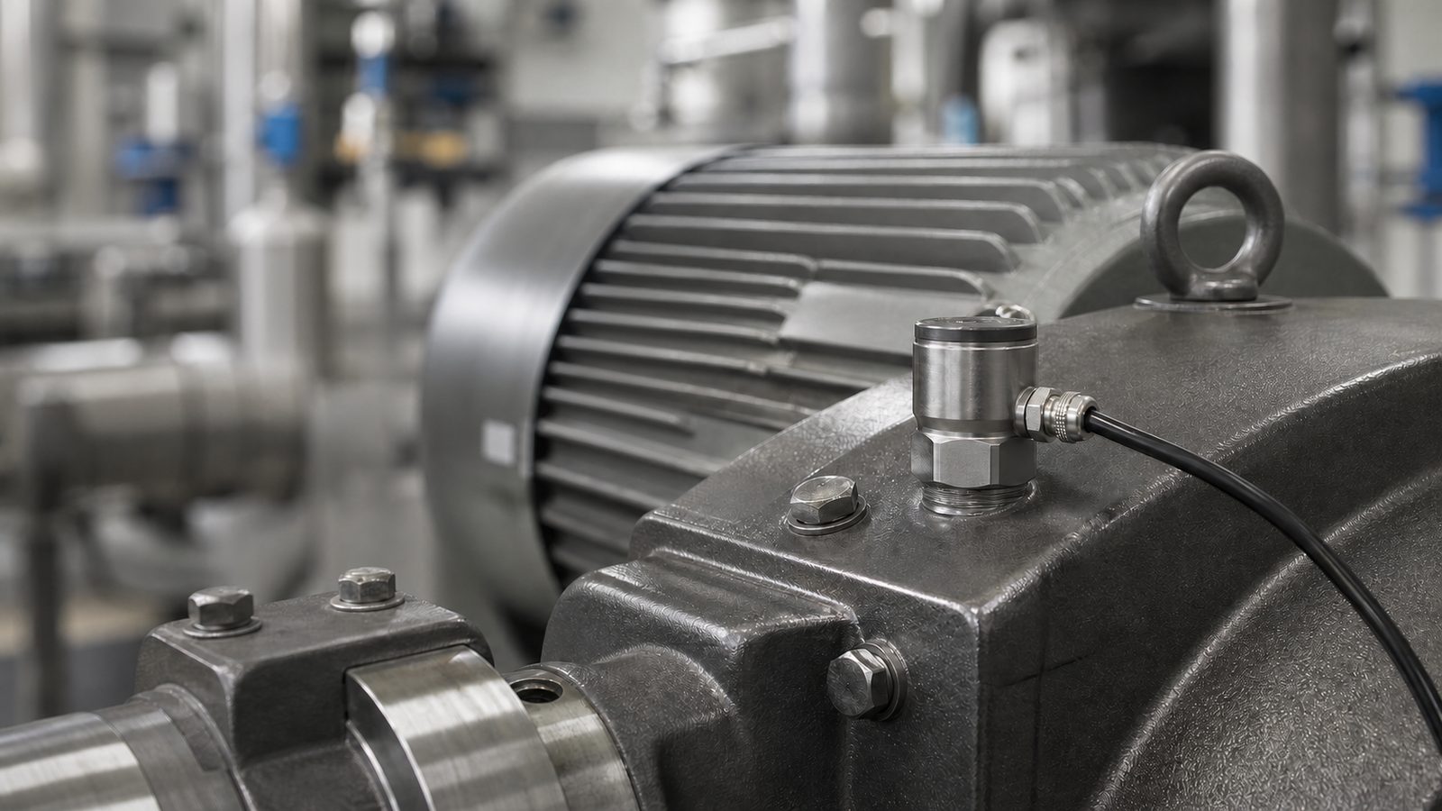
The node mounts to the asset housing and reads vibration and temperature continuously. A MEMS accelerometer and an RTD feed an analog front end sized for the amplitude range of the target equipment class. Rather than stream raw waveform data, the node runs the frequency-domain transform at the edge and reports spectral features, band energies, and temperature. Full-resolution capture is pulled on demand when something looks wrong, which keeps the routine data volume small enough to matter for both power and network load.
Connectivity was treated as a variable, not an assumption, because the client sells into whatever infrastructure the customer already has. Bluetooth Low Energy handles commissioning and configuration at the asset: a technician pairs from a phone, sets the node up, and leaves, with no network credentials and no IT ticket. Backhaul is then selected per site at commissioning across WiFi, Ethernet, LoRa, and cellular, rather than forcing a different product variant for each customer. A plant with good WiFi coverage uses it. A remote station with no network of its own uses cellular. A large yard, or structure that defeats 2.4 GHz, uses LoRa. Sites that will not put process data on any wireless link use wired Ethernet. Data buffers locally when the link is down, so an outage delays the record instead of losing it.
The enclosure is sealed for washdown areas and mounts with a threaded stud or an adhesive pad depending on the asset, so a retrofit takes minutes on a running machine. On the software side we delivered the ingest path and a baseline model that learns each asset's normal signature over its first weeks of operation, instead of shipping fixed thresholds that generate nuisance alarms and get switched off.
Continuous monitoring on assets that previously had none, installed without interrupting production and commissioned by a service technician rather than an integrator. The client moved from calendar-based visits to condition-based dispatch, which changed the economics of their service contracts.
Any asset base where failures are expensive, access is inconvenient, and existing monitoring is manual: process plants, water utilities, commercial HVAC, and fleet-deployed equipment.
03
In a recirculating aquaculture system, water exchange is one of the largest recurring operating costs after feed and power, and exchange volume tends to be set conservatively because the alternative is risking stock. That was the situation here. Water quality was managed by manual sampling several times a day with operators dosing by judgment, so parameters drifted between checks, corrections overshot, and the safety margin was held by flushing more water than the biology strictly required.
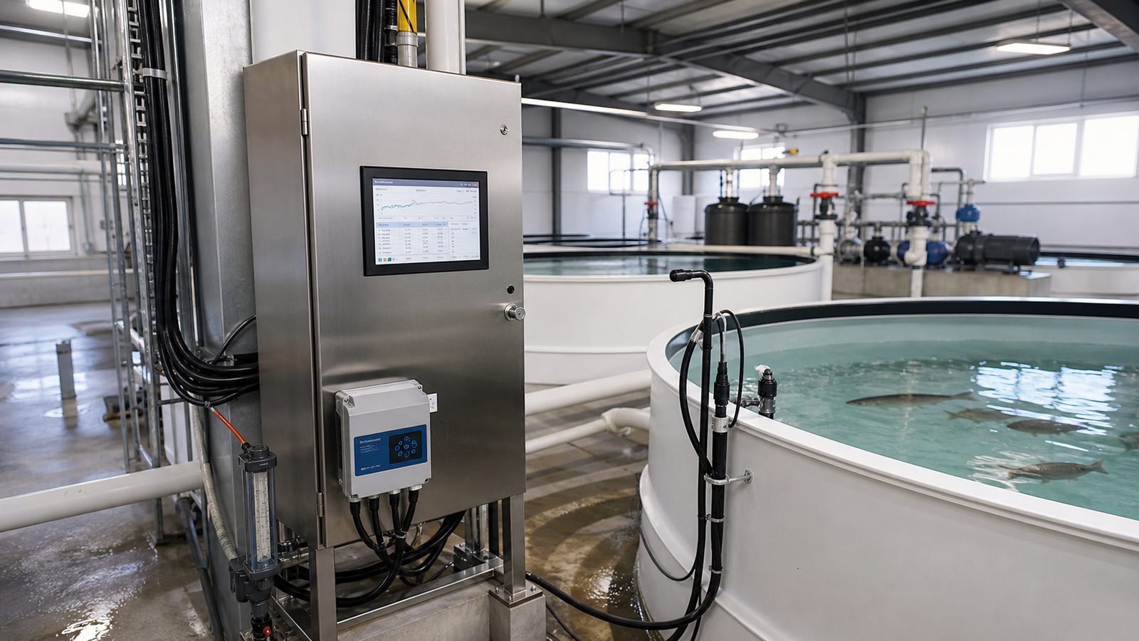
We instrumented the loop for continuous measurement of dissolved oxygen, pH, temperature, oxidation-reduction potential, and total ammonia nitrogen. Making continuous TAN measurement behave in a working system is the hard part of this build, and it is what makes the water saving possible: nitrogen loading sets how much water actually has to be exchanged, and if you cannot see it you have to assume the worst case. Probe placement was chosen so readings represent tank conditions rather than local mixing artifacts, with calibration prompts and drift detection built in, because a quietly failing sensor here is more dangerous than an obviously failed one.
Control moved from operator judgment to closed loop. Oxygen injection, pH correction, and biofilter feed rate follow the measured state of the system, with rate limits and interlocks that stop a large correction being made on a single bad reading. Water exchange became a function of measured nitrogen loading rather than a fixed schedule.
Communications were built for a working facility. A wired Ethernet backbone carries the controller, operator interface, and site systems in the equipment room, where a process-critical link should not depend on radio conditions. WiFi covers the tank deck and puts the system on a tablet while an operator is standing at the tank rather than back at the panel. Bluetooth Low Energy handles commissioning and calibration at the probe itself, which matters more than it sounds: calibration is the recurring maintenance task in a RAS loop, and making it a two-minute job at the tank is what keeps it from being skipped. If the controller loses communication, the system falls back to a defined safe state under manual override rather than holding its last command.
A marked reduction in makeup water use, with tighter parameter stability than manual dosing achieved. The system reached production and is in operational use, not a pilot. Reduced exchange also cut the heating and pumping energy that comes with bringing new water up to temperature. Operators moved from sampling rounds to exception handling.
The comparison is makeup water per kilogram of feed input, the standard normalization for recirculating systems, measured against the same loop on its previous manual schedule at equivalent stocking density, feed rate, and temperature. Normalizing to feed rather than elapsed time matters, because feed drives nitrogen loading and nitrogen loading sets the exchange requirement.
Closed-loop process control where the controlled variable is biological or chemical rather than purely electrical: aquaculture, water treatment, fermentation, and greenhouse fertigation.
04
The client inspected a molded component visually at end of line. Two operators per shift examined parts under a lamp, judged surface and dimensional defects, and sorted by hand. Throughput was capped by how fast a person can reliably look at a part, escape rates varied by operator and by hour of shift, and there was no record of what had been rejected or why, which made root-cause work on the molding process largely guesswork.
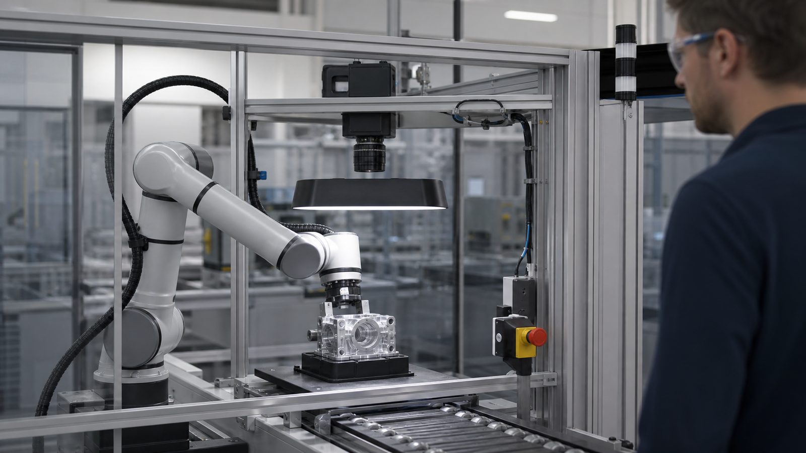
The feasibility phase came first, and it mattered. We imaged known good and known defective parts under several lighting geometries before committing to a design, because most vision projects that fail do so at the lighting stage, not the algorithm stage. Low-angle directional lighting resolved the surface defect class; a separate backlit station handled the dimensional checks. Optics were selected to hold resolution across the part's depth variation.
Classification uses conventional metrology for dimensional features, where the pass criteria are numeric and auditable, and a trained model only for the cosmetic defect classes where rule-based logic had proven brittle. That split matters for a regulated customer audit: the dimensional result can be explained without reference to a model.
Part presentation and sorting are handled by a robot fed from the existing conveyor, with the cell exchanging state and results with the line PLC over the plant's existing industrial Ethernet protocol. Every part inspected is logged with its images and its measured values, so the process engineers finally had defect data tied to time, cavity, and shift.
A large increase in inspection throughput over the manual station, with consistent criteria applied across all shifts and a defect record that supported process improvement upstream. The two operators moved to higher-value work rather than being displaced. False-reject rate was tuned during validation against a sample set the client's quality team assembled, not against our own test images.
High-volume inspection where human judgment is the bottleneck or the source of variance: molded and machined parts, assembly verification, packaging, and electronics.
These four are a sample. If what you're building isn't represented here, ask — we'll talk through the projects nearest to your problem, within what confidentiality allows.
Start a project